Vacuum is a utility used in a vast array of industrial manufacturing processes including packaging, bottling, drying, degassing, pick and place to name but a few. An industrial vacuum pump is used for creating, improving and maintaining vacuum in these processes. There are many types of industrial vacuum technologies available and this article will explore those technologies. To understand which type of vacuum is most suitable for you and your application, it is crucial to understand the features, benefits and operating principle each type of technology. This article will review the most common types of industrial vacuum pump, how they work and in what types of applications they are best suited.
Basic Operating Principle of an Industrial Vacuum Pump
The basic operating principle of an industrial vacuum pump remain the same no matter the technology type.
Vacuum pumps remove air molecules (and other gases) from the vacuum chamber (or the outlet side in the case of a higher vacuum pump connected in series). As the pressure in the chamber is reduced, removing additional molecules becomes increasingly harder to remove. Therefore, an industrial vacuum system must be able to operate over a portion of an extraordinarily large pressure range, typically varying from 1 to 10-6 Torr / 1.3 to 13.3 mBar of pressure. In research and scientific applications this is extended to 10-9 Torr or lower. To accomplish this, different types of pumps are used in a standard vacuum system, each covering a proportion of the pressure range, and operating in series at times.
Pressure Ranges of Industrial Vacuum System
Industrial Vacuum systems can be placed into the following groups of pressure ranges:
- Rough/Low Vacuum: 1000 to 1 mbar / 760 to 0.75 Torr
- Fine/ Medium Vacuum: 1 to 10-3 mbar / 0.75 to 7.5-3 Torr
- High Vacuum: 10-3 to 10-7 mbar / 7.5-3 to 7.5-7 Torr
- Ultra-High Vacuum: 10-7 to 10-11 mbar / 7.5-7 to 7.5-11 Torr
- Extreme High Vacuum: < 10-11 mbar / < 7.5-11 Torr
Different types of pumps for these vacuum ranges can then be divided into Primary (Backing) Pumps, Booster Pumps and secondary (High Vacuum) Pumps: High, very high and ultra-high vacuum pressure ranges.
There are two basic categories of vacuum pump: Gas Transfer Pumps and entrapment or capture pumps.
Gas Transfer Pumps
Transfer Pumps transfer gas molecules by either momentum exchange (kinetic action) or positive displacement. The same number of gas molecules are discharged from the pump as enter it and the gas is slightly above atmospheric pressure when expelled. The compression ratio is the ratio of the exhaust pressure (outlet) to the lowest pressure obtained (inlet).
Kinetic Transfer Pumps
Kinetic transfer pumps use high speed blades or introduced vapor to direct gas towards the outlet, working on the principle of momentum transfer. These types of pump can achieve high compression ratios at low pressures but typically don’t have sealed volumes.
Positive Displacement
Pumps which work by mechanically trapping a volume of gas and moving it through the pump are known as positive displacement pumps. Often designed in multiple stages on a single drive shaft, the isolated volume is compressed to a smaller volume at a higher pressure, and finally the compressed gas is expelled to either atmosphere or the next pump. To provide a higher vacuum and flow rate two transfer pumps are often used in series.
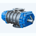
As mentioned previously, positive displacement vacuum pumps are used to create low vacuums. This type of vacuum pump, expands a cavity and allows the gases to flow out of the sealed environment or chamber. After that, the cavity is sealed and causes it to exhaust it to the atmosphere. The principle behind positive displacement vacuum pump is create a vacuum by expanding the volume of a container. For example in a manual water pump, a mechanism expands a small sealed cavity to create a deep vacuum. Because of the pressure, some fluid from the chamber is pushed into the pump’s small cavity. After that, the pump’s cavity is then sealed from the chamber, opened to the atmosphere and then squeezed back to a minute size. Another example of positive displacement vacuum pumps is like a diaphragm muscle expands the chest cavity, causing the volume of lungs to increase. This expansion results to creating a partial vacuum and reducing the pressure, which is then filled by air pushed in by atmospheric pressure. The examples of positive displacement vacuum pumps are liquid ring vacuum pumps and roots blower which are highly used in various industries to create vacuum in confined space.
Entrapment Pumps
Pumps which capture gas molecules on surfaces within the vacuum system are unsurprisingly known as, Capture or Entrapment Pumps. These pumps operate at lower flow rates than vacuum pumps such as transfer pumps, however, they can provide extremely high vacuum, down to 10-12Torr. Capture pumps operate using cryogenic condensation, ionic reaction, or chemical reaction and have no moving parts, therefore creating oil-free vacuum.
Those Entrapment Pumps that work using chemical reactions, perform more effectively as they are usually placed inside the container where vacuum is required. Air molecules create a thin film which is removed as the pumps operation cause a chemical reaction to the internal surfaces of the pump. Entrapment pumps are used along with positive displacement vacuum pumps and momentum transfer vacuum pumps to create ultra-high vacuum.
Wet or Dry Vacuum Pumps – An Overview
Vacuum pump technologies are considered either wet (lubricated) or dry (oil free or dry running), depending on whether or not the gas is exposed to oil or water during the compression process.
Wet pumps lubricate and/or sealing themselves using either oil or water; this fluid can contaminate the pumped (swept) gas. Whereas, Dry vacuum pumps have no fluid in the pumped gas, relying on precise clearances between the rotating and static parts of the pump, dry polymer (PTFE) seals, or a diaphragm to separate the pumping mechanism from the gas and ensure a tight seal.
However, dry are not completely oil-free, as oil or grease is often used in the pump gears and bearings. This is kept separate from the vacuum compression side. Dry pumps reduce the risk of contamination and oil mist. They also have environmental benefits of not requiring the disposal of oils like lubricated pumps.
Centrifugal pumps
Centrifugal pumps are hydraulically operated machines characterised by their ability to transmit energy to fluids (in particular to liquids) through the work of a field of centrifugal forces. Their main purpose is to transfer fluids through an increase in pressure. Centrifugal pumps can have different structures, but their operating principle and fluid dynamic characteristics are always the same.
Liquid Ring Vacuum Pumps
Liquid ring vacuum pumps are similar to a rotary vane pump, with the difference being that the vanes are an integral part of the rotor and churn a rotating ring of liquid to form the compression-chamber seal. They are an inherently low-friction design, with the rotor being the only moving part. Sliding friction is limited to the shaft seals. Liquid-ring pumps are typically powered by an induction motor.
More About Liquid ring Technology
Rotary Claw
Rotary Claw vacuum pumps generate contact-free vacuum efficiently and economically. This is possible because of the principle of internal compression in the rotary claw design. The claw vacuum pumps are based on a static compression system. In contrast to rotary lobes, compression happens internally by volume contraction.
A claw pump consists of two rotors. They turn in opposite directions in a compressor housing without contact observing very tight clearances. They are synchronised via a precision gear. As the claw moves over the suction connection and the axial suction channel inlet gas is sucked into the compression chamber. The gas is pre-compressed within the compressing chamber and is then discharged.
Rotary screw pumps
A screw vacuum pump consists of two parallel, screw-shaped rotors, one with a right-hand thread and the other with a left-hand thread. Both screws turn in the compressor housing without friction and at very tight clearances.
They are synchronized via a precision gear. The compression housing and the special shape of the screws form the compression chambers. Due to the opposite rotation of both screws the chamber connected with the suction port is enlarged and the gas is transported into the compression chamber. Then the chamber moves axially from the suction side to the pressure side (arrow).
In variable pitch models, the gas is compressed at each pitch change and cooled before the next pitch change, resulting in greater efficiency. On the pressure side the chamber is moved against the axial housing wall and the volume is reduced until the front surface of the screw opens the pressure channel and the pre-compressed gas is discharged through the pressure connection. Cooling is achieved using a water cooled outer chamber. For some pump sizes additional cooling gas can be introduced into the pump.
Side Channel Blowers
Side Channel Blowers have an impeller mounted directly on the motor shaft for contact free compression. The gas is taken in through the inlet. As it enters the side channel, the rotating impeller imparts velocity to the gas in the direction of rotation. Centrifugal force in the impeller blades accelerates the gas outward and the pressure increases.
Every rotation adds kinetic energy, resulting in further increase of pressure along the side channel. The side channel narrows at the rotor, sweeping the gas off the impeller blades and discharging it through the outlet silencer where it exits the pump.


